Introduction to Survey Design Wizard Version 4.1
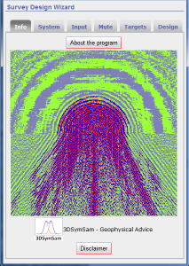
3DSymSam’s Survey Design Wizard (SDW) is meant as an assistant to the design of 3D seismic surveys. It provides parameters for orthogonal geometry.
 The calculations are based on symmetric sampling theory as discussed in “3D seismic survey design” by Gijs J.O. Vermeer (SEG, 2002, 2012). In this new version a more realistic formula may be used to compute offset for a given stretch factor. This formula is described in Vermeer, 2013, “NMO stretch in survey design and processing“, SEG, Expanded Abstracts. It links maximum required angle of incidence (for AVO-analysis) directly to shot-receiver offset.
There are two versions of the SDW, a standalone version and an online version. Both versions were written by Willem Vermeer of WilPower. The standalone version is written in Java and may be run on Windows or Apple pc’s. A zip file with the standalone version may be downloaded here. The online version may be run by clicking the link at the bottom of this page.
The SDW provides the basic 6 parameters that are needed to specify regular orthogonal geometry. These parameters are: 1 and 2) station interval for both shots and receivers (these values are the same because of reciprocity), 3 and 4) the (integer) number of receiver stations between shot lines and number of shot stations between receiver lines (these integers determine the line intervals), and 5 and 6) inline fold and crossline fold (these integers determine maximum inline offset and maximum crossline offset). The SDW also computes some dependent parameters, assuming a one-line roll of the designed template that consists of a number of shots situated in the middle of a swath of receiver lines. This is the so-called nominal geometry; other implementations such as full-swath roll are always possible based on nominal geometry, provided the complete nominal geometry can be extracted from the acquired data (see for more details Vermeer, 2012).
The design provided by the SDW is based on specific requirements for up to three targets (shallow, mid, and deep) and on a representative velocity distribution. It also needs the maximum NMO stretch factor the user is willing to accept for the longer offsets. The mute function is computed on basis of the velocity distribution and the maximum stretch factor. The mute function itself is used to determine the maximum useful offset for each target. In its turn this offset plays a role in the determination of fold for each target.
The user has to provide the velocity function in a text file (format specified in SDW help file) and (s)he may also provide a file “system.text” with suitable defaults for the various parameters. These parameters may be modified interactively.
The program consists of a number of tabs or pages that have to be stepped through in sequence. Each page has its own Help text accessible via clicking the “?”. The last page “Design” provides four different designs. Design 1 is always a fully symmetric solution that satisfies most requirements and the three other solutions are small permutations of the symmetric solution. The user may change the station spacing for all four Designs; then new solutions are found for line intervals and for maximum offsets. The user may also change station interval and the four integers to generate her/his own design and to analyze the variations in dependent parameters because of that.
The help files will guide the first-time user through the program.
Go to Survey Design Wizard
